I had my first thoughts of wanting to do something with our doorbell a few years ago after we added our first smart home devices and tried to get a Ring doorbell, but it was too bulky to fit on our doorframe.
This idea remained vague until I saw a YouTube video, probably over a year ago, about how to turn an old doorbell into a smart home button. Once I saw that video, I knew I wanted that project to be my first foray into the world of small electronics, a world I have watched on YouTube for many years, waiting for the time to get into it.
The project was appealing because:
- It looked (relatively) simple, yet it was still a chance to do something that wasn’t just a premade kit.
- We needed it. When someone presses our doorbell, the only thing that happens is a pretty quiet and hard-to-hear buzzer buzzes. We often don’t hear it. There was a second bell, but that got removed during a remodel. We didn’t reinstall it because we figured we would get one of those smart doorbells.
- I liked the idea of the old reliable technology continuing to work (as well as it had been), whether my overly complicated smart home system was working or not.
Once I decided to make this doorbell project a “priority”, it took me about six months of very sporadic progress. To begin, I knew I needed a “board”. I had a couple of Arduino boards sitting around from project kits I’d started several times before getting distracted and forgetting most of what I’d learned before picking them up again. I got back into it and got “Hello World!” and made an LED blink, working again.
Upon examining my specific situation and where the doorbell components were physically located, I learned it was a good news, bad news situation.
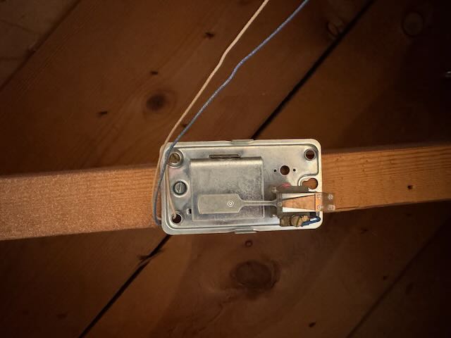
Good news: The buzzer was easy to find, in the drop ceiling of my basement.
Bad news: In a different video about a similar project, they tapped into the “mains AC” to power the board. However, all I had were the low-voltage wires running to the buzzer. I tried to track the wires back to the “transformer”, but despite much effort, I couldn’t find it. I suspect it is in an inaccessible place.
More bad news: There are no power outlets in the drop ceiling near the buzzer or along where the wire for the doorbell goes.
Good news: I have a PoE switch with some open ports and have run Ethernet through the basement’s drop ceiling in the past to where my switches live.
More good news: I’m not the first person who has wanted one of these dev boards with PoE. There are a few options.
Even more good news: The Hubitat hub I’ve been using as the brains for my smart home system makes it (pretty) easy to set up a virtual button that can be “pushed” by hitting an HTTP endpoint.
The Plan:
- Buy an “AC Current Transformer”, which detects the current.
- Buy a “dev board” with PoE.
- Run Ethernet cable from my PoE switch to right next to my doorbell buzzer.
- Program the dev board to detect current in the wire when the doorbell is pressed and then push the virtual doorbell in my Hubitat.
- After confirming functionality, mount the hardware next to my doorbell buzzer tidily.
At some point, I decided to use an ESP32 dev board because they had a bit more horsepower, and any extra current they’d draw isn’t a big issue because they have a good power source via the PoE.
One small step back: The first ESP32 board I ordered did not have PoE. I got over-eager and ordered a board before realising I wouldn’t have power where I wanted the board to be.
I received my (round 2) parts in the mail. It turned out the AC Current Transformer needed assembling, with soldering, which I had never done before.
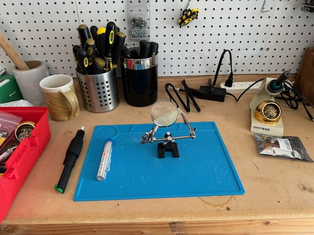
After watching a few soldering videos, I bought some equipment. It was a bit rough, but I got the hang of things after a few tries. I have seen enough videos on small electronics and sensors to know that you should never (hardly ever) buy just one of something. It usually costs about the same to buy 5 or 20 as it does to buy 1, and you might get a faulty part, make a mistake, or they might just not work, and you’ll never know exactly why.
I think my second attempt at assembling the sensor looked as though it should work. So it was time to try programming the dev board. I spent a lot of time trying to program the board with the Arduino IDE. It did not go well. After a while I gave up. It probably is a perfectly good board, but it did not have enough documentation to get me started. I went back to the Internet, and quickly found a suitable dev board from Olimex with plenty of documentation. So, I ordered a couple of those. Eventually, they arrived, and I faced the same programming issues. After some conversations with ChatGPT and web searches, I tried lowering the baud rate at which I was programming the board to 115200. That did it. That was probably the reason the second board I ordered didn’t work either.
I’m sure a little more knowledge would have helped a lot. But as far as I can tell, those who frequently engage in this kind of work tend to find a couple of dev boards they like and are comfortable with, using them as much as possible.
Finally, I was able to program the board and debug it. The code I needed to write (or copy/paste/tweak) was less than a page long and (compared to so many of the other steps in this process) “just worked.”
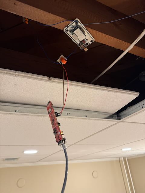
While waiting for my third round of dev boards to arrive, I watched the video again and realised I would be working with AC voltage and should be careful. At this point, I had basically accepted that every step in this process would require many iterations, and I should make that as simple as possible. So, I also ordered some wire, and after some research, learned about these Wago connectors. As far as I can tell, this was a good application Wagos, and I put a couple on the wire going to the doorbell buzzer. I’m glad I did that; it made things a lot easier.
However, before unscrewing/cutting wires, I wanted to turn off the power to the doorbell. And sure enough, finding which breaker the doorbell was on turned into an hour-long project. It would have helped if I’d enlisted some help, but I thought/hoped it was one of a couple of breakers. It was not. I did end up with a much better picture of what the breakers control though. I think I tried almost all my breakers.
It was time for a fully working prototype, and without too much fiddling, it worked! I was so happy, full of confidence and ambition, which I should probably have curbed. I got to thinking I should make a nice case for this. I got a 3D printer a couple of months ago, and it’s been a lot of fun to print other people’s designs. Maybe I should design a custom case for my hardware.
I started exploring 3D modelling for 3D printers. Wow, that’s a lot. I tried Fusion 360, watched a couple of videos. It looks amazing but is clearly designed for people who use Fusion 360 five days a week for at least four hours. The same was evident about Blender. Eventually, I found OpenSCAD, a code-driven CAD programme. Given my background (I’ve even done a tiny bit of 3D graphics), I was more comfortable with it, and they had a very nice tutorial to get me started.
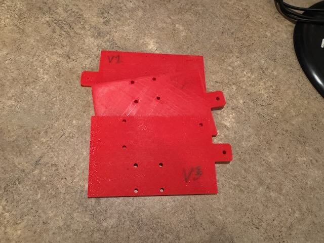
After learning how much 3D design is not a field one simply “walks into”, I decided I was not going to make a case but a mounting board. After a few attempts to get the screw holes to line up, I gave up on that and just made bigger holes to strap the components onto. I did manage to make some little mounting screw holes on the ends of the board, which worked well.
At last, it was time to put it all together. And, of course, it did not work. Every time I tried to boot up my code (which worked before), the board would crash (or so I thought). I considered that the newer version of the Arduino IDE might be causing problems. That was not it. I had to do more soldering to put the pins on the dev board. Maybe I messed something up there, shorted something or whatever; the solder was a little lumpy. Maybe there was a short. I tried my hand at solder removal and did my best to clean things up. At some point in the process, I realised things worked fine if the sensor was not plugged in. Of course, it didn’t work, but it was able to boot up and get a network connection. I can’t remember what inspired this line of inquiry; it might have been good old ChatGPT advising me to “Read the manual”.
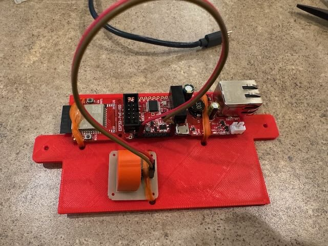
I started looking at the diagram of the pins and their functions. It turned out I was using a GPIO pin that said it was “free.” But what does “freedom” really mean? I found something about how this GPIO0 pin was on the ADC2, which also serves the wireless chips. Was that the problem? I don’t know. But when I saw that GPI35 was on ADC1, well, that was all I needed to try that pin and see what happened. Sure enough, it worked! Hooray!
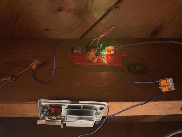
I suspect the reason it actually worked was because it was an “input-only” pin, and maybe if I had set things up correctly in the “sketch”, it might have all worked fine. I also wonder if something strange happened to the board during my ministrations.
I’ve had it installed for a couple of weeks now, and it’s been working great. I’m still experimenting with what I want it to do in my smart home system. Right now, it just sends a notification to mobile phones, and that’s been helpful on several occasions.